Design of Traffic Light System
| ✅ Paper Type: Free Essay | ✅ Subject: Engineering |
| ✅ Wordcount: 708 words | ✅ Published: 30 Aug 2017 |
Contents
Complete Block Diagram of the traffic light system
Circuit simulation using Multisim software,
Figure 13 (Main red and amber sub amber)
LIST IN Tab;e
List in Figure
Figure 1: traffic lights system
Figure 4 (main red and sub green for 10s)
Figure 5 (Main amber and sub red and amber for 2s)
Figure 6(main red and sub green for 10s)
Figure 7 (Asynchronous counter for timing counter)
Figure 8(The Design is 30s counter for main road in Asynchronous counter)
Figure 9 (The Design is 20s counter for side road in Asynchronous counter)
Figure 10 Main green and sub red
Figure 11 (Main amber and sub red and amber)
Figure 12 (Main red and sub green)
Figure 13 (Main red and amber sub amber)
Design Specification
Design specification prepared for a single main and sub -road junction in rural area is given below
- The green light for the main road will be stay ON for 30s.
- The green light for the side road will be stay ON for 20s.
- The amber caution light will say ON for 5s between changes from green to red.
- Main road and side road timing countdown should display in a 7segment display.
- Sequence change of the traffic lights show in the Appendix I.
The traffic light system for a single main road and sub road junction in a rural area.


Complete Block Diagram of the traffic light system


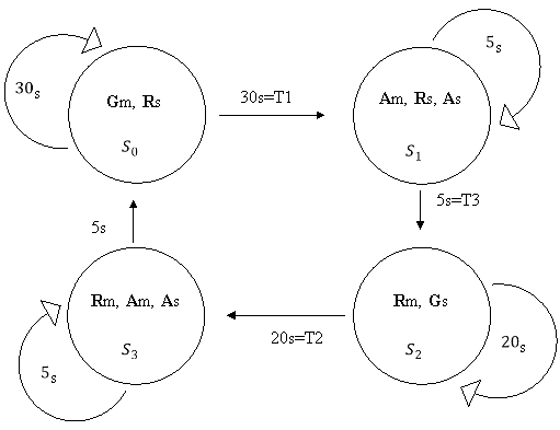
The FSM description stands for “Finite state machines”. the Finite state machines are the most common controllers of machines. It’s In the example Traffic light, the intersection of a main road with a side road is controlled by two traffic lights. FSM has three inputs (T1, T2 and T3) AND six outputs (Rm, Am, Gm, Rs, As and Gs)
In here
Rm is Red light for main road
Am is Amber caution light for main road
Gm is Green light for main road
Rs is Red light for sub road
As is Amber caution light for sub road
Gs is green light for sub road
T1 time is 30seconds
T2 time is 20seconds
T3 time is 5seconds
Complete Moore model state diagram for traffic light system
State diagram Table
|
P.State |
N.State |
INPUT |
Outputs |
|||||
|
Gm |
Am |
Rm |
Gs |
As |
Rs |
|||
|
|
|
|
1 |
0 |
0 |
0 |
0 |
1 |
|
|
T1 |
|||||||
|
|
|
|
0 |
1 |
0 |
0 |
1 |
1 |
|
|
T3 |
|||||||
|
|
|
|
0 |
0 |
1 |
1 |
0 |
0 |
|
|
T2 |
|||||||
|
|
|
|
0 |
1 |
1 |
0 |
1 |
0 |
|
|
T3 |
|||||||


State Assignment in Gray code
Here using gray code for states


State transection table
Here using D type flip flops for design a circuit
|
P.S Q1 Q0 |
N.S Q1+ Q0+ |
INPUT |
||||||||
|
|
|
Gm |
Am |
Rm |
Gs |
As |
Rs |
|||
|
0 0 |
0 0 |
|
0 |
0 |
1 |
0 |
0 |
0 |
0 |
1 |
|
0 1 |
T1 |
0 |
1 |
|||||||
|
0 1 |
0 1 |
|
0 |
1 |
0 |
1 |
0 |
0 |
1 |
1 |
|
1 1 |
T3 |
1 |
1 |
|||||||
|
1 1 |
1 1 |
|
1 |
1 |
0 |
0 |
1 |
1 |
0 |
0 |
|
1 0 |
T2 |
1 |
0 |
|||||||
|
1 0 |
1 0 |
|
1 |
0 |
0 |
1 |
1 |
0 |
1 |
0 |
|
0 0 |
T3 |
0 |
0 |


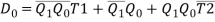
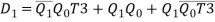
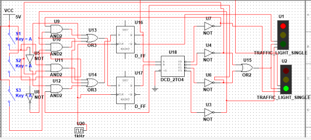
Simplified equations for the system.


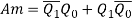
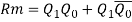

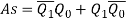
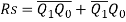

(


The equations are,


Circuit simulation using Multisim software,
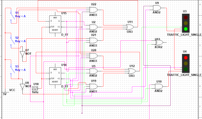
Figure 4 (main red and sub green for 10s)
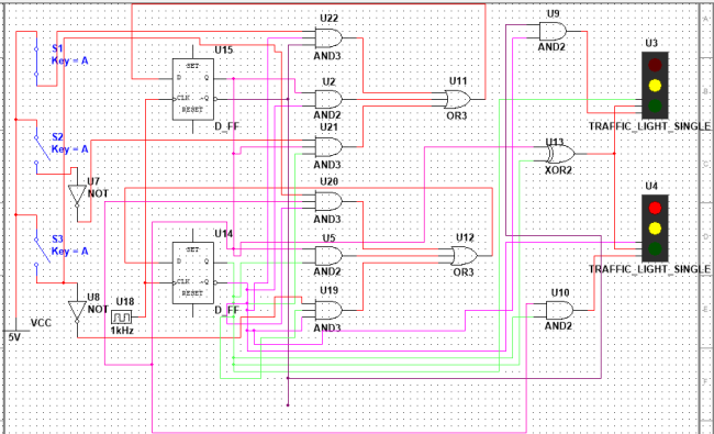
Figure 5 (Main amber and sub red and amber for 2s)
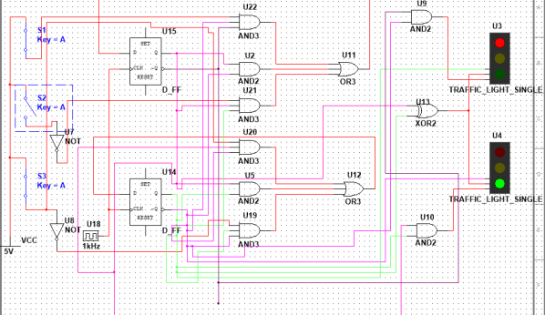
Figure 6(main red and sub green for 10s)
Timing Counter

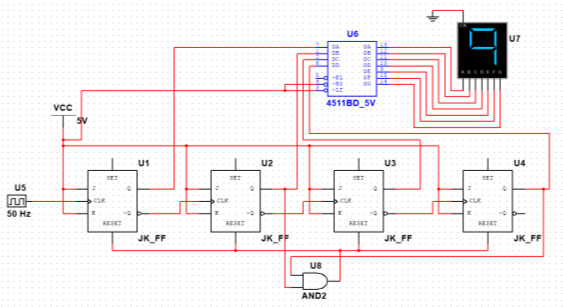


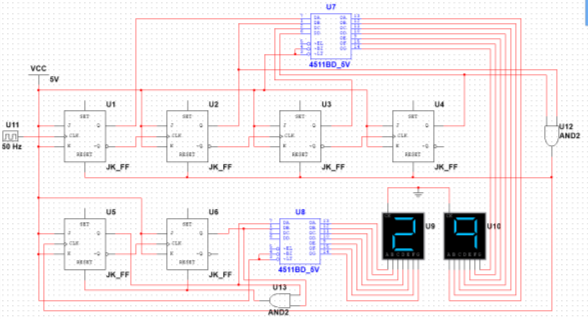
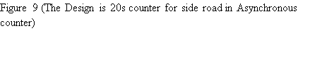
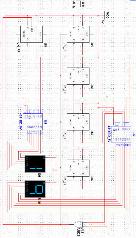
Figure 10 Main green and sub red
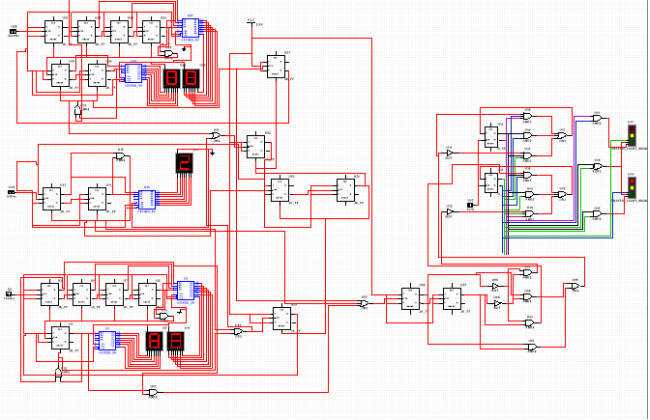
Figure 11 (Main amber and sub red and amber)
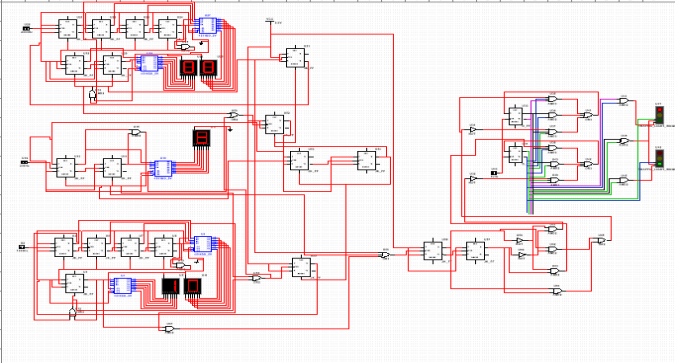
Figure 12 (Main red and sub green)
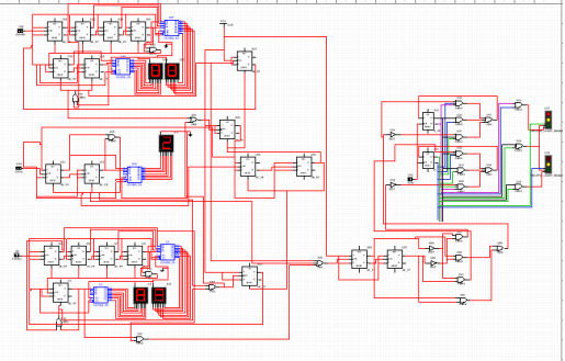
Figure 13 (Main red and amber sub amber)
Task 4
|
Item name |
quantity |
Price (Rs) |
|
2 pin AND gate IC |
5 |
120Ã-5=600 |
|
3 pin AND gate IC |
2 |
120Ã-2=240 |
|
2 pin OR gate IC |
1 |
40Ã-4=40 |
|
3 pin OR gate IC |
1 |
40Ã-1=40 |
|
2 pin XOR gate IC |
1 |
40Ã-1=40 |
|
Dual JK FF IC |
10 |
100Ã-10=1000 |
|
Dual D FF IC |
1 |
100Ã-1=100 |
|
DCD 7 Segment decoder IC |
5 |
100Ã-5=500 |
|
7 Segment display |
5 |
50Ã-5=250 |
|
NOT gate IC |
2 |
40Ã-2=80 |
|
Red color LED |
2 |
5Ã-2=10 |
|
Amber color LED |
2 |
5Ã-2=10 |
|
Green color LED |
2 |
5Ã-2=10 |
|
wires |
20m |
15Ã-20=300 |
|
Power adaptor |
2 |
150Ã-2=300 |
|
Total |
3420 |
|
Remake design
Compare the cost
|
Item name |
Previous cost (Rs) |
New cost(Rs) |
|
2 pin AND gate IC |
1Ã-120 = 120 |
1Ã-120 = 120 |
|
3 pin AND gate IC |
1Ã-120 = 120 |
0 |
|
XOR gate IC |
1Ã- 40 = 40 |
0 |
|
D type FF IC |
1Ã-100 = 100 |
1Ã-100 = 100 |
|
Decoder IC |
0 |
1Ã-100 = 100 |
|
NOT gate IC |
1Ã- 40 = 40 |
2Ã- 40 = 40 |
|
OR gate Ic |
1Ã- 40 = 40 |
1Ã- 40 = 40 |
|
total |
460 |
400 |
- In new design cost is less than old design
Reference
ïƒ˜ï€ Mano M.M,Michael D.C. (2008).Digital Design.New Delhi:PHI.
ïƒ˜ï€ Floyd,L.(2011).Digital Fundamentals.10th ed.India:Pearson. p271- 287.
ïƒ˜ï€ http://www.topssrilanka.com/article24948-new-traffic-ligth-system-atbambalapitiya.html.Lasr
ïƒ˜ï€ http://www.sundayobserver.lk/2012/06/03/imp01.asp
Cite This Work
To export a reference to this article please select a referencing stye below:
Related Services
View all


DMCA / Removal Request
If you are the original writer of this essay and no longer wish to have your work published on UKEssays.com then please click the following link to email our support team:
Request essay removal