Causes of Material Failure
| ✅ Paper Type: Free Essay | ✅ Subject: Engineering |
| ✅ Wordcount: 2391 words | ✅ Published: 30 Aug 2017 |
Safety, reducing weight and maintenance costs of structural components, have always been a target in structural design, particularly where lighter structures result in higher load carrying capacity in industrial projects (Li et al. 2003). Since the high strength steel (HSS) is susceptible to weld defects, specifically in structures subjected to alternating stresses, the bolted connections are used as an effective and versatile joining technique in a variety of structures compared to welded equivalents (Jiménez-Peña et al. 2016). In this respect, various authors have investigated the performance of bolted joints under static loading condition. Despite this, the behavior of bolted joints under cyclic loading is still not well documented and fully understood (Mínguez and Vogwell 2006).
A deep concern that engineers have regarding the serviceability of commercial structures is the detrimental failure resulting from metal fatigue. As a matter of fact, the design philosophies have changed over recent years in a way that static strength has been replaced by fatigue life, durability and damage tolerance (Mínguez and Vogwell 2006). Design rules for bolted connections are available in Canadian and American standards in conjunction with extensions for fatigue design considerations.
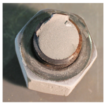
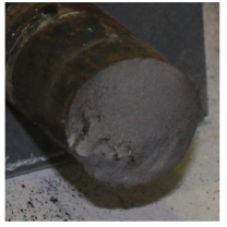
Material failure happens in several forms, such as wear, corrosion, deformation, and fracture. When a component is subjected to a cyclic loading and results in the separation of the component into two or more pieces, this is plain fatigue or conventional fatigue. On the other hand, fatigue failure might occur due to a phenomenon known as fretting fatigue (Hämäläinen and Björk 2015). For example, one of the bolts that connects the bottom bracket to the support broke was fractured due to fretting fatigue and another was failed because of plain fatigue during the round four of accelerated fatigue test under 113 kN at 2 Hz of fatigue as shown in Fig. 1 and Fig. 2. Therefore, it proves why an extensive research should be undertaken to investigate the precise mechanism of fretting fatigue in bolted connections.
Fretting can occur when a pair of structural components are in contact under a normal load while cyclic tangential stress and relative displacement are applied alongside the contact surface. The phenomenon of fretting has been recognised initially as a surface damage phenomenon, what today are called fretting wear. During fretting the fatigue strength decreases to less than one-third of that without fretting (Hattori et al. 2011). This kind of fatigue can be seen widely in bolted and riveted connections. The fatigue life performance of bolted joints depends on several factors, such as size of the bolts, the number and arrangement of used bolts, the level of pretension or torque tightening applied to the bolts, the material plate thickness and surface roughness. Understanding in what way all these factors affect the fatigue life of a joint is fairly complex and has not been thoroughly investigated (Mínguez and Vogwell 2006).
The primary objectives of this literature review are (1) to review a comprehensive understanding of the underlying mechanisms lead to fretting fatigue failure; (2) to determine the factors which influence the fatigue strength of bolted joints; (3) to indicate predictor tools used in order to estimate the fatigue lifetime of bolted joints; (4) to propose different approaches to address the aforementioned objectives.
|
Fig. 1: Plain fatigue in bolt shank and fretting fatigue in bottom surface of bolt head |
|
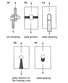
Bolted connections are classified on basis of the mechanism in which the forces are transferred. When members are not pressed together by torque tightened bolts, the joint members can move freely (bearing-type bolted connection); thus, a large portion of load is transferred from bolt to the edge of plates as shown in Fig. 3. Elongation of the holes due to the stress transmitted through the bolts into the members might occur, if the stress levels within the hole are adequately high to cause plastic deformation. In this case, the major failure modes for a joint subjected to shear loading would be as shown in Fig. 4. On the other hand, when the plate members are compressed together by application of tightening torque on the bolts, the members
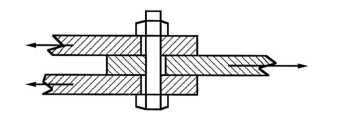
Fig. 3: A bearing joint, with the bolt acting as a shear pin
slippage could be prevented; therefor, the friction in contact interface transfers loads directly, instead of transmitting through the bolt to the plates hole. In this way, the connections benefit greatly with respect to the failure modes presented in Fig. 4, because the stress concentrations caused by the bearing of the bolts at the edge of plates hole will be lowered significantly (friction-type bolted connection). Fig. 5 illustrates the behavior of a friction-type joint under static loading in shear. The joint deforms elastically until the load reaches the critical value. At region (2) the joint begins to slip and it continues until the bolts start bearing on bolt holes. Elastic deformation happens again in region (3), until the yielding of plates or bolts occurs in form of plastic deformation in region (4). Eventually, joint will be failed at point (5) (Mínguez and Vogwell 2006).
|
|
|

The phenomenon of plain fatigue refers to the behavior of materials under the action of repeated stress and strain which distinguishes it from their behavior under monotonic or static stresses or strains. The plain fatigue is defined more precisely by the process in which the progressive localized permanent structural changes occur in a material subjected to conditions that produce fluctuating stresses and strains at some points and that culminate in cracks or complete fracture after a sufficient number of fluctuations. A plain fatigue failure is often very sudden, with no obvious warning; however, the mechanism might have been operating from the beginning of the component’s usage.
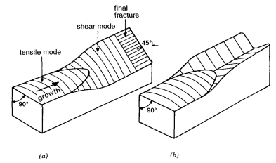
Fig. 6: Crack growth path in sheet (a) single shear (b) double shear
Fig. 6 shows fatigue crack initiation and propagation schematically. At short crack length where crack tip plastic zones are small, the crack path is usually flat. As crack grows, the crack tip plastic zone increases in size and the crack plane can turn to 45° shear or slant mode. This can be either single shear as shown in Fig. 6(a) or double shear as shown in Fig. 6(b). The aspects of plain fatigue fracture can be summarized as follows:
- The entire fatigue process involves the nucleation and growth of a crack or cracks to final fracture.
- The plain fatigue crack at fracture can be very small or very large, occupying less than 1 percent of the fracture up to almost 100 percent.
- The plain fatigue crack region can be distinguished from final fracture region by beach marks, smoothness, and corrosion, However, there are many exceptions.
- Microscopic plain fatigue cracks often grow in the plain of maximum tensile stress. However, for multiaxial loading, macroscopic fatigue cracks have also been observed on the plane of maximum shear (Stephens et al. 2000).
It is one century since the problem of fretting first has undergone scientific investigation. Fretting was recorded first by Eden, Rose and Cunningham in 1911, who observed a red rust in the grips of fatigue machines by which they were testing steel specimens. The removal of the specimens was encumbered by the rust and its formation was mainly attributed to the varying stress between specimens and grips. This phenomenon was experimentally investigated first via Tomlinson in 1927, and coined the term ” fretting wear” by which name it is generally known today (Scott 2013). Intensive study of the fretting process and mechanism has been undertaken during the 1950s and 1960s. Various theories regarding the nature of fretting have been summarized by Hurricks and then published in 1970. In 1974 Golego et al. recapitulated the results of experimental and analytical investigations conducted in the Soviet Union and other countries (Kovalevskii 1981).
Based on these meticulous and intensive investigations, it appeared that the problem of fretting fatigue has adequately been solved, and it is of least interest. At the end of the 1930s and the beginning of 1940s fretting was observed in a new form, as a rapid lowering of the fatigue strength of metals. Warlow-Davis was the first scholar who studied the effect of fretting corrosion on fatigue life. Numerous investigations regarding this complicated phenomenon have been carried out subsequently, and interesting and informative results were obtained on basis of empirical and factual observations. Fretting fatigue has generally been considered in terms of the contribution of fretting to the fatigue strength of material. The recognition and interpretation of mechanism of fretting fatigue by means of this approach is more difficult. It thus appears more reasonable to attempt to postulate the mechanism of fretting fatigue on basis of a combination of the basic theory of fretting wear and the fatigue failure of metals (Kovalevskii 1981).
Fretting maybe defined as surface damage caused by low amplitude oscillatory sliding between two contacting surfaces. Fretting fatigue and fretting wear lie within this broad definition. Fretting is divided into two categories: fretting wear and fretting fatigue. The removal of material from contacting surfaces through fretting action is called fretting wear, whereas fretting fatigue is the reduction in fatigue life due to fretting surface damage (Bill 1983). Both types often occur within the same contact, but in different areas. Partial slip region is the area where contact pressure caused by normal force is high, while displacement amplitude caused by alternating tangential force is relatively small. In these areas, possibly fretting occurs as fatigue. On the other hand, those areas of the contact where the displacement amplitude is somewhat large compared to contact pressure are called gross slipping regime. In these areas fretting happens as fretting wear. There is another regime between these two regimes in a way that both mechanisms overlap, mixed fretting regime. Running condition fretting map is a useful tools (RCFM) used to present these regimes and the effect of those in the specimen failure can be translated into a material response fretting map (MRFM). Fig. 7 shows the schematic illustration of these maps (Hämäläinen and Björk 2015).
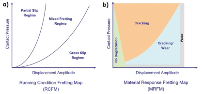
Fig. 7: Schematic illustrations of (a) running condition fretting map (b) material response fretting map
Fretting fatigue is a complicated tribological behavior of components which are in contact together having a small relative oscillatory motion. Due to high stress gradients generated at interface of connected surface caused by fretting, the fatigue lifetime of materials is reduced considerably compered to plain fatigue (Hojjati-Talemi et al. 2013). Fretting often occurs in structures subjected to oscillating tangential loads with low-amplitude and high frequency vibrations. Since fretting happens in counterpart surfaces, where crack initiation and crack propagation is hidden, and there is no easy access for inspection, crack detection is often impossible; hence, it is a particularly dangerous phenomenon. Sometimes the development of fretting damage is not detected until critical fracture or even catastrophic failure is occurred (Hoeppner 2006). Consequently, fretting fatigue heightens a serious concern for industrial structures, and analytical and numerical techniques for prediction of fretting fatigue are much in demand. Fig. 8 illustrates an example of failure due to fretting.
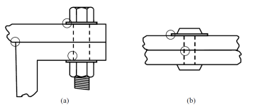
Fig. 8: Typical critical locations for fretting fatigue crack initiations in (a) bolted flange and (b) riveted panels
4.1 Fretting wear and fretting fatigue-How are they related?
The extent to which fretting wear correlates fretting fatigue is not fully cleared. The surface damage and contact stress distribution are similar in fretting fatigue and fretting wear for a given set of contact conditions. The remarkable feature which is evident in fretting fatigue, while is not for fretting wear necessarily, is an alternating bulk stress in one of the contact bodies. Furthermore, the edges of contact area or near slip/nonslip interfaces are the spots where fretting fatigue occurs consistently. The sequence of crack initiation and propagation in fretting problems involving fretting wear or fretting fatigue is important, because it generally causes microspalling in the former case and fatigue failure in the later (Bill 1983).
Fig. 9 presents the loading conditions for a typical fretting contact. The significant feature which distinguishes fretting from gross sliding wear is the formation of a partial slip zone within the contact area when the tangential force is less that the frictional force.
|
|
Eq. 1 |

The small displacement amplitude traps the wear debris and prevents those from existing contact zone. Different combinations of normal load and displacement lead to different forms of damage mechanism. Another comprehensive fretting maps proposed by Vingsbo in 1988 is plotted schematically in Fig. 10. The area is divided into various regimes and the dominant damage mechanism is specified in each zone as following:
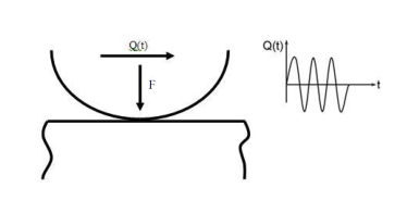
Fig. 9: Fretting contact and loading
- Partial slip regime or Stick regime: Although some slip occurs by application of tangential loading, most of the contact zone remains in stick. Fretting fatigue is the dominant mode of failure in this area; however, some wear occurs even when reciprocating motions are as small as 0.25 µm.
- Mixed stick and slip regime or mixed fretting regime: This regime is categorized by transition of the fretting contact from partial slip to the gross sliding. The dominant mode depends on whether the fatigue cracks grow fast enough to avoid removal by wear.
- Gross slip regime or gross sliding regime: Slip exists throughout the contact in this regime. The excessive volume of debris produced by fretting cycle, would prevent crack from propagating. Although the slip happens all around the contact, the debris formed during fretting cycle would trapped within contact area. This is a fundamental characteristic which distinguishes this regime from reciprocating sliding phenomenon.
- Reciprocating sliding: Once the amplitude meets a critical level, the wear mechanism will be similar to unidirectional sliding. The remarkable feature of reciprocal sliding wear is that for different amplitudes within reciprocal sliding, wear volumes is almost being kept constant, whereas the production of oxidized debris and a wear coefficient would increase rapidly by the increase of amplitude of motion (Patil 2010).
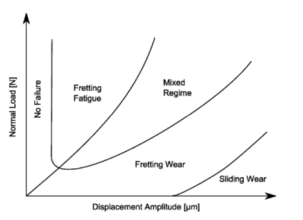
Fig. 10: Typical fretting map for Hertzian contact
Although, it is very difficult to establish a precisely distinct line of demarcation between fretting wear and reciprocal sliding wear, some literatures suggest that the critical amplitude of slippage in which the occurrence of reciprocating sliding wear will be imminent. Due to complexity of fretting phenomenon, different refrences presented different transition values for different materials. Vingsbo and Soderberg in 1988 as well as Ohmae and Tsukizoe in 1974 suggested the transition value lies at 300 µm, Toth suggested 50 µm, while Lewis and Didsbury concluded transition value equal to 70 µm (Chen and Zhou 2001).
Cite This Work
To export a reference to this article please select a referencing stye below:
Related Services
View all


DMCA / Removal Request
If you are the original writer of this essay and no longer wish to have your work published on UKEssays.com then please click the following link to email our support team:
Request essay removal