RBG Colour Model Experiment
| ✅ Paper Type: Free Essay | ✅ Subject: Computer Science |
| ✅ Wordcount: 751 words | ✅ Published: 18 Aug 2017 |
Introduction
Color is a visual attribute of objects that results from the light they emit, transmit or reflect. [1] These colors give us the ability to appreciate things around us. With this, we can easily define or give meaning to the things we see almost every day. We can see these colors in paintings, surroundings, the food we eat, and almost everything, as almost everything has color. Electronic systems use different color models to represent data visually. [2] One of these color models is RGB color model. A color in RGB color model is expressed by how much of each red, green, blue is included [2], hence the acronym RGB. In this experiment, we lit the RGB LED with different colors in Arduino, with the use of RGB color model.
Materials with Description
- DFRduino Uno R3 (1)
The arduino circuit board.
- Jumper Cables M/M (4)
Serves as the connector to different pins in the circuit.
- RGB LED (1)
A diode that emits light and to be used as an output in the circuit. It provides different colors of light by setting its RGB (Red, Green, Blue) values. It consists of 3 anodes, one for each color in RGB, and one cathode.
- 220 Ω Resistor (3)
An electric device that will control the flow of current through the circuit.
Procedure (self-explained)
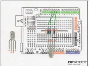
- Connect the components to the breadboard base on the tables below.
|
Resistor |
Breadboard |
|
|
Start |
End |
|
|
A |
D9 |
G9 |
|
B |
D7 |
G7 |
|
C |
D6 |
G6 |
Table 1 Resistor Positions
|
RGB LED |
||||
|
Red |
Cathode(-) |
Green |
Blue |
|
|
Breadboard |
I9 |
I8 |
I7 |
I6 |
Table 2 RGB Led Position
|
Jumper Wires |
Breadboard |
Arduino |
|
|
Start |
End |
||
|
1 |
C6 |
– |
DP 10 |
|
2 |
C7 |
– |
DP 11 |
|
3 |
C9 |
– |
DP 9 |
|
4 |
H8 |
– |
GND |
Table 3 Jumper Wire Positions
- After plotting the components to the breadboard. Connect the USB cable to the computer and the circuit.
- Compile and upload the code.
Circuit Diagram
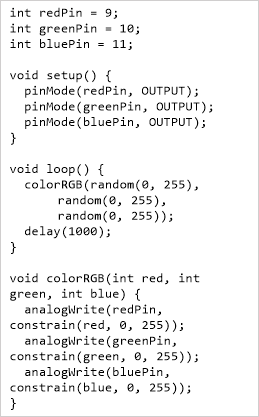 Code
Code
Code Analysis
“int redPin, greenPin, bluePin” this code sets the pin numbers of each color from RGB LED to their respective pin slot in the Arduino.
“void setup(){…}” a one-time initialization method. Set all redPin, greenPin, and bluePin as output by using pinMode(pin, pinType) built-in function.
“void loop(){…}” a method that constantly iterates the statements inside the block. In this experiment, we created different colors, by generating random numbers from random(min, max) each color from red, green and blue.
“random(0, 255)” a built-in function that generates random number from range 0 to 255.
“void colorRGB(int r, int g, int b){…}” a user-defined method that accepts values of r, g, and b. This method is also responsible for assigning the values/colors for the pins of the RGB LED by using analogWrite(pin, value). When these colors are combined together, the RGB LED will create a different color based on the values of the RGB written by analogWrite().

“constrain(value, min, max)” a built-in function that checks whether value is in the range of min and max. If so, return the value. If value is greater than max, this function will return max. If value is less than min, this function will return min. This code is essential to check whether the value is less than 0 or greater than 255, as analogWrite can only accept values 0-255. Also, the color values for each color in RGB can only be 0 – 255. For example: R = 255, G = 0, B = 255, this will create a violet color.
“delay(n);” lets the circuit sleep or pause for n milliseconds.
Comparison of Code vs. Hardware Output
It is noticeable that the code controls and manages how will the hardware provide an output. It is also important that the pins used in the hardware should be the same in the code. This experiment introduced a new kind of LED that can represent or display different colors. The RGB LED changes its color by using random number generation as part of the code, and setting those values to each color in RGB pins in the LED.
Recommendation/Enhancement
The experiment can be integrated in disco bars, to produce different colors of lights. This can be also used for medical purposes for people who may suffer color blindness. For example, an RGB LED, will produce colors, and the individual will describe the color he or she saw. A billboard composed of multiple RGB LEDs can be used to act like as pixels in a graphic image.
|
[1] |
“WordNet Search – 3.1,” [Online]. Available: http://wordnetweb.princeton.edu/perl/webwn?s=color&sub=Search+WordNet&o2=&o0=1&o8=1&o1=1&o7=&o5=&o9=&o6=&o3=&o4=&h=. |
|
[2] |
“RGB Color Model – Wikipedia,” [Online]. Available: https://en.wikipedia.org/wiki/RGB_color_model. [Accessed 9 January 2017]. Cite This WorkTo export a reference to this article please select a referencing stye below:
Reference Copied to Clipboard.
Reference Copied to Clipboard.
Reference Copied to Clipboard.
Reference Copied to Clipboard.
Reference Copied to Clipboard.
Reference Copied to Clipboard.
Reference Copied to Clipboard.
Related ServicesView allDMCA / Removal RequestIf you are the original writer of this essay and no longer wish to have your work published on UKEssays.com then please click the following link to email our support team: Request essay removalRelated Services Our academic writing and marking services can help you! Freelance Writing Jobs Looking for a flexible role? Study Resources Free resources to assist you with your university studies! |


