VLSI Architecture for QR Decomposition on MHHT Algoritm
| ✅ Paper Type: Free Essay | ✅ Subject: Communications |
| ✅ Wordcount: 2683 words | ✅ Published: 18 Jul 2018 |
A VLSI Architecture for the QR Decomposition based on the MHHT Algorithms.n.v.sai.pratap1 k.kalyani2 s.rajaram3
|
Abstract:
This paper presents Novel VLSI (Very Large Scale of Integration) architecture for the QR decomposition (QRD) based on the Modified Householder transformation (MHHT) algorithm. QRD of a matrix H is decomposition of matrixHinto a productof an orthogonal matrix Qand an upper triangularR. QRD is often used to solve several engineering problems in many areas. Pre-processing modules based on QRD makes the decoding in signal processing easier and implementing data detection with QRD helps to reduce the complexity of spatial multiplexing MIMO – OFDM detection. The techniques used for implementing QR decomposition are: Givens rotation, Modified GramSchmidt Orthogonalization (MGS), Householder Transformations (HHT), and indeed Modified Householder transformation (MHHT). The proposed MHHT algorithm shows best trade-off between complexity and numerical precision, and also suites for VLSI architectures. The proposed MHHT algorithm reduces computation time and hardware area of the QRD block compared to the existing Householder algorithm. Implementation of this algorithm is carried out in FPGA Virtex6 xc6vlx550tl-1Lff1759 device with the help of Xilinx ISE 14.1.
Keywords: MIMO systems,VLSI architecture, QR Decomposition (QRD), Householder Transformation(HHT).
1. INTRODUCTION:
The QR decomposition (QRD) is a basic matrix factorization method from matrix-computation theory used to compute two output matrices Q and R from an input matrix H, such that H = QR. QRD is often used to solve many engineering areas like least-square problems, linear system equations etc. For symbol-decoding solutions inside Spatial-Multiplexing Multiple-Input Multiple-Output (SM-MIMO) systems, QRD basically consists in simplifying demodulation tasks in suboptimal and near-optimal solutions by finding an orthogonal matrix Q and an upper-triangular matrix R from an input matrix H. Several techniques towards implementing the QRD are already reported in literature. For instance, and under the context of SM-MIMO systems, the most explored are the Modified Gram-Schmidt Orthogonalization (MGS, as a generalized improvement of the Gram-Schmidt algorithm), Givens rotation, the Modified Householder Transformations (MHHT as an enhancement of the Householder Transformation algorithm). Due to its simplicity and numerical stability, the QR factorization algorithm utilizing Householder transformations has been adopted. An overview of the main steps of the Existing Householder QR algorithm is presented. The purpose of this work is to show that when modifying existing Householder QR factorization to the matrix H, the computational complexity and hardware area gets reduced. Due to its trade-off in complexity, numerical precision, and VLSI implementation suitability, the MHHT is preferred. The contribution of this paper is to present a flexible and scalable FPGA-based VLSI architecture with competitive capabilities against other related approaches, motivated on the context of SM-MIMO demodulation solutions.
The organization of this paper is as follows:
Section II presents the QRD. In Section III, the exisiting HHT and MHHT algorithm is exposed. Implementation results are reported in Section IV, and conclusions are covered in Section V.
2. QR DECOMPOSITION
The QRD constitutes a relevant pre-processing operation in SM-MIMO demodulation tasks [1-2]. The baseband equivalent model can be described in
 (1)
(1)
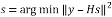
At each symbol time, a vector S with each symbol belonging to the Quadrature Amplitude Modulation (q-QAM) constellation passes through the channel response matrix H. The received vector y at the receiving antenna for each symbol time is a noisy superimposition of the signals contaminated by Additive White Gaussian Noise (AWGN) given by n.The maximum likelihood (ML) detector is the optimum detection algorithm for the MIMO system. It requires finding the signal point  from all transmit vector signal sets that minimize the Euclidean distance with respect to the received signal vector
 . The transmitted symbol s can be estimated by solving
 (2)
(2)
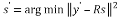
This gives the optimal result. However, solving (2) with larger constellations and multiple antennas will result in complex calculations. Instead of solving (2) as such, the symbol estimation can be simplified by using QR decomposition of .That is where resides the usefulness of decomposing matrix H in a QR form, yielding a back-recursive dependency on elements in S without incurring into a BER (Bit Error Rate) loss [3-4]. With this practice, the computational complexity is reduced. The detected vector
  is computed based on the ML algorithm with QR decomposition as given in (3)
 (3)
(3)
where 
 is in upper triangular form, approximation of
  is computationally simpler with the aid of (3). Note that for MIMO-OFDM systems operated in stationary environments, the channel matrix remains almost the same. Thus, QR decomposition of the channel matrix can be done only once to get matrix
 . On the other hand, the calculation of
  must be updated for every incoming signal
 .
.
2.1 QRD IMPLEMENTATION
The techniques used for QR decomposition are:
Gram–Schmidt algorithm obtains the orthogonal basis spanning the column space of the matrix by the orthogonality principle. Using a series of projection, subtraction, norm and division, the column vector of the unitary matrix containing the orthogonal basis can be acquired one by one and upper triangular matrix is also obtained as a by-product. Householder Transformation (HHT) tries to zero out the most elements of each column vector at a stroke by reflection operations. The upper triangular matrix is derived after each transformation matrix being applied to every column vector sequentially. The unitary matrix involves the multiplications of these Householder transformation matrices and thus the complexity is much higher. On the other hand, Givens Rotation (GR) zeros one element of the matrix at a time by two-dimensional rotation. If an identity matrix is fed as an input, the unitary matrix will be calculated by using the same rotation sequence when the upper triangular matrix is obtained (Malstev 2006; Hwang 2008 and Patel 2009).The Gram–Schmidt algorithm has the disadvantage that small imprecisions in the calculation of inner products accumulate quickly and lead to effective loss of orthogonality.HHT method has greater numerical stabilitythan the Gram–Schmidt method. Givens method stores two numbers c and s, for each rotation and thus requires more storage and work than Householder method .Givens rotation requires more complicated implementation in order to overcome this disadvantages. Givens rotation can be beneficial for computing QR factorization only when many entries of matrix are already zero, since nullifying certain matrix elements can be skipped. Unlike Givens Transform, Householder Transform can act on all columns of a matrix, and require less computations for Tridiagonalization and QR decomposition, but cannot be deeply or efficiently parallelized. Householder is used for dense matrices on sequential machines, while Givens is used for sparse matrices or/on parallel machines.

3. QRD using Householder Transformation
In this section, the existing Householder Transformation algorithm is described, followed by proposed HHT method architecture is demonstrated in detail.
3.1 Householder Transformation
Householder QR algorithm gradually transforms H into an upper triangular form R by applying a sequence of Householder matrices (multiplies H from the left with Q). Householder transformation is performed by projecting a multi-dimensional input vector onto a plane zeroes multiple elements at the same time. An n×n matrix H of the form
 , (4)
, (4)
is called a Householder matrix. The vector  is called a Householder vector. Pre-multiplication of the coefficient matrix
  with
with  is used to zero out appropriate elements of
 . It is easy to verify that Householder matrices are symmetric and orthogonal.
The Householder matrix block involves the computation of an outer product which requires
  complexity operation. However, the practical time requirement of using
  to zero out elements in
  is lower than that of computing a full outer product. This is because of the tedious computation of the full matrix which is not necessary in practice.
Householder reflections work well for introducing large number of zeros using just one matrix multiplication (computing ). Normally, all the elements below the diagonal of an entire column of the matrix are eliminated by one Householder reflection. However, this leads to a difficulty when Householder transforms are implemented on parallelly. One reflection affects multiple rows, and therefore, it is difficult to achieve fine-grained parallelism in the operation.
The algorithm for Householder transform is given in Table 1. and its block diagram is given in Figure 2.
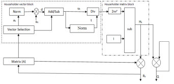
Fig. 2 Block diagram of HHT
Table 1 HHT algorithm
|
End |


Householder vector block:
The conventional method of Householder algorithm for decomposing channel matrix is given in Table 1. Initially, the channel matrix is assigned to matrix . It can be periodically updated by following steps to obtain upper triangular matrix. The first column of is assigned to ‘a’ vector. After that the norm value of ‘a’ is calculated and assigned it to ‘g’. The Householder vector ‘v’ is the division ‘u’ and‘t’ which is the norm operation of vector selection .
Householder matrix block:
The output of Householder vector is given as input to Householder matrix block. Finally, H is computed by 
The above operation can be updated upto n times to obtain the upper triangular matrix and unitary matrix. It is given below,
 (5)
(5)
Q = (HnHn-1…H1) T (6)
Here the matrix  is given to the input of channel matrix to update its vector value. The orthogonal matrix
  is computed by the multiplication of ‘n’ Householder matrix. Hence its complexity increases and also it occupy more hardware area. If the matrix size increases, the hardware area also increases tremendously. So there is need to reduce the hardware complexity of this block.
3.2 Proposed HHT method
The existing method of Householder reflection requires large hardware area and computation time. Householder transformations also provide the capability of nullifying multiple elements simultaneously by reflecting a multi-dimensional input vector onto a plane. However, VLSI implementation of the Householder algorithm needs square-root, multiplication and division operations, which require high hardware complexity. To resolve this issue, a novel Householder algorithm is presented that use series of simple Householder projections, which can be easily implemented using simple arithmetic operations.
The proposed algorithm as given in table2 has lesser number of computations compared to the existing algorithm. In Figure 3, the block diagram of modified method is given. It shows two major sub blocks (i.e.) householder vector block and householder matrix block. Householder vector block is same to the previous method of computing ‘v’ with extra weight vector computation. Here modification taken in the Householder matrix block to eliminate matrix multiplication. The vector ‘v’ subtracted from ‘f’ and column vector of channel matrix to give ‘H’ value.
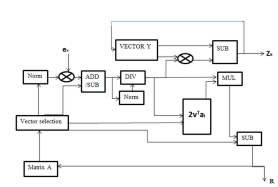
Fig. 3 Block diagram of MHHT.
In the first step, matrix H is reduced to  with all zeros below the diagonal element in the first column by computing the sign of the pivot element d and weight value w. Compared to the previous algorithm, number of steps required to obtain the first matrix can be reduced. For example, if the initial channel matrix of 4×4 undergone to Householder reflection, then it reduces the matrix with all zeros below the first element. The computation of Householder vector
  in the existing algorithm requires large memory and area. Because is a 4×4 matrix, multiplication of
  become complex process. To avoid such a task, column vector of matrix
  has been taken one by one and process it iteratively to obtain the upper triangular matrix. After computation of the first step the matrix size reduced to
 . After that, the sub matrix of size 3×3 is taken and the steps can be applied repeatedly.
The algorithm to compute Householder Vector block is given below.
Table 2 HHT algorithm
|
End Repeat above steps for right bottom (n-1)*(n-1) matrix of R |


Householder vector block:
In this Householder reflection algorithm, it transforms the column
 (7)
(7)
into the vector of the form
 (8)
(8)
where the diagonal element
 (9)
(9)
The Householder vector can be computed by,
 (10)
(10)
where 
and 
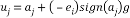
This block computation is same as that of previous Householder vector block with a little modification in the weight value.
Householder matrix block:
After obtaining the Householder vector, the output vector is given to the input of Householder matrix block. The computation of this block is very simple compared to previous method of Householder matrix block computing. The Householder matrix element algorithm is given below,
 (11)
(11)
where 
It reduces the channel matrix to its upper triangular form in  steps. To reduce the complexity of computing Q, here the output vector y’ has been taken directly and its algorithm is given below,
 (12)
(12)
So the execution time for computing the upper triangular matrix and output vector is very less when compared to conventional Householder reflection algorithm. This reduces the hardware area for the Householder matrix block. The QR decomposition using modified Householder transformation algorithm is simulated by taking ‘a’ as input channel matrix, ‘zb’ as output vector and ‘upper’ as upper triangular matrix. The unitary or orthogonal matrix ‘Q’ need not to be calculated. The output vector  in (3) can be computed from the updated Householder vector ‘v’. Also the extra time needed to calculate ‘Q’ can be reduced. So the speed of decomposing the channel matrix can be increased tremendously.
4. Results and Discussion
QR decomposition algorithm is required as a pre-processing unit for many MIMO detectors. The accuracy of the channel matrix QR decomposition does not have an impact on the MIMO detection process and finally receiver’s bit-error-rate (BER) performance. The existing and proposed Householder algorithms are downloaded on to Xilinx device xc6vlx550tl-1Lff1759. The synthesis results are compared to show the area efficiency of the proposed one.
The channel matrix H elements are represented in floating point representation of 16 bits comprising 1 for sign bit,3 bits for decimal part and 12 bits for fractional part. The 16 bit representation shows an numerical precision oscillates around the interval[10-6,10-5] for both existing and modified algorithms .
The computation of column vectors of the R matrix can be parallelised in modified algorithm and thus improvement is obtained in computational time of 49.7% reduction.The computational time for proposed algorithm is about 194.84ns,whereas exisiting algorithm is about 394.56ns.
Modified algorithm reduces the matrix computation into vector multilications for some extent and thus reduces the hardware area as obtained from the synthesis report.
Table 3 Synthesis report for Conventional Householder algorithm
|
Logic Utilization |
Used |
Available |
|
Slice LUTs |
11142 |
343680 |
|
Bonded IOBs |
768 |
840 |
|
BUFG/BUFGCTRL’S |
0 |
32 |
|
DSP48E1s |
261 |
864 |
Table 4 Synthesis report for Proposed Householder algorithm
|
Logic Utilization |
Used |
Available |
|
Slice LUTs |
7634 |
343680 |
|
Bonded IOBs |
385 |
840 |
|
BUFG/BUFGCTRL’S |
1 |
32 |
|
DSP48E1s |
70 |
864 |
Table 5 Comparison result
|
Logic Utilization |
Conventional HHT |
Proposed HHT |
% reduced |
|
Slice LUTs |
11142 |
7634 |
31% |
|
LUT Flip flops |
768 |
385 |
49.8% |
|
Bonded IOBs |
0 |
1 |
—— |
|
DSP48E1s |
261 |
70 |
73% |
5. Conclusion
To reduce the computational and hardware complexity, Householder transformation algorithm for QRD has been modified. The computation of Q is the tedious process in the existing algorithm. In this work, it can be overcome by directly computing output vector. It reduces the computation time by 52.38% and also reduce in hardware area compared to previous HHT algorithm (Slices – 31%, LUTs – 49.8%) presented in the QRD. Thus it is evident from the comparison result that the number of slices and 4 input LUTs required in FPGA implementation of QR Decomposition is reduced thereby making the low complex design which can meet the specifications of most OFDM communication systems, including VDSL, 802.16, DAB and DVB. In future, this work can be extended to implement K-best LSD and Turbo decoding of LTE receiver.
References
- Lee, K.F. and Williams, D.B.: A space-frequency transmitter diversity technique for OFDM systems. In Proc. Global Telecommunications Conf., San Francisco, CA, pp. 1473-1477. (Nov. 2000)
- H. Kim, J. Kim, S. Yang, M. Hong, and Y. Shin, “An effective MIMO–OFDM system for IEEE 802.22 WRAN channels,” IEEE Trans. Circuits Syst. II, Exp. Briefs, vol. 55, no. 8, pp. 821–825, Aug. 2008.
- H.-L. Lin, R. C. Chang, and H.-L. Chen, “A high speed SDM-MIMO decoder using efficient candidate searching for wireless communication,” IEEE Trans. Circuits Syst. II, Exp. Briefs, vol. 55, no. 3, pp. 289–293, Mar. 2008.
- L. Boher, R. Rabineau, and M. Helard, “FPGA implementation of an iterative receiver for MIMO–OFDM systems,” IEEE J. Sel. Areas Commun., vol. 26, no. 6, pp. 857–866, Aug. 2008.
- M.-S. Baek, Y.-H. You, and H.-K. Song, “Combined QRD-M and DFE detection technique for simple and efficient signal detection in MIMO–OFDM systems,” IEEE Trans. Wireless Commun., vol.
- 8, no. 4, pp. 1632–1638, Apr. 2009.
- C. F. T. Tang, K. J. R. Liu, and S. A. Tretter, “On systolic arrays for recursive complex Householder transformations with applications to array processing,” in Proc. Int. Conf. Acoustics, Speech, and Signal Process., 1991, pp. 1033–1036.
- K.-L. Chung and W.-M. Yan, “The complex Householder transform,” IEEE Trans. Signal Process., vol. 45, no. 9, pp. 2374–2376, Sep. 1997.
- S. Y. Kung, VLSI Array Processors. Upper Saddle River, NJ, USA: Prentice-Hall, 1987.
Cite This Work
To export a reference to this article please select a referencing stye below:
Related Services
View all


DMCA / Removal Request
If you are the original writer of this essay and no longer wish to have your work published on UKEssays.com then please click the following link to email our support team:
Request essay removal