Acoustics and Critical Listening: Studio Design
| ✅ Paper Type: Free Essay | ✅ Subject: Architecture |
| ✅ Wordcount: 4383 words | ✅ Published: 23 Sep 2019 |
Home Studio Design
Contents
2. Architectural and Sound Isolating Properties
2.5 Other Techniques for Room Isolation and Noise Reduction
4.1 Reflections and Reverberation Time
4.2 Absorption and absorption coefficients
5.1 Placement Angle and Height
1. Introduction
This report focuses primarily on the creation of both a usable and optimal studio space for the modern day, while discussing the key principles of acoustics that influence the choices and decisions made in the design. The format of the report takes on that of a guide, informing and discussing different concepts, methods and design choices for building a studio from the ground up.
2. Architectural and Sound Isolating Properties
The Architectural properties of a building greatly impacts sound inside the room and can also provide varying amounts of room isolation. Room isolation refers to how much sound can travel in and out of the room, with greater isolation meaning less sound leakage, this sound leakage is commonly referred to as noise and comes in two main types; airborne noise and structure-borne noise. Airborne Noise is sound which flows in and out using small gaps in the building’s architecture where air flows. Airborne noise can disrupt a studio environment by bringing noise from outside. Structure-borne noise refers to noise which primarily travels through solids within the building’s structure, these are low frequency sounds which can travel long distances through solids due to their high density.
Another term used in relation to room isolation is the TL value.
The TL value refers to “sound transmission loss (TL) effectiveness” (Allegion 2018), which means to how many decibels a sound pressure level is reduced when passing through an object (in decibels). Transmission loss is frequency dependant and the equation to find the TL value at different frequencies is:
Figure 1.1 “TL = 14.5 log Mf – 16” (David Miles Huber, Robert, E. Runstein., 2010).
Where M = surface density in pounds per square foot (lb/ft)
and TL = transmission loss (dB)
and f = frequency (Hz)
from this, the conclusions can be made that the TL value rises with frequency, and “heavier acoustic barriers will yield a higher transmission loss” (David Miles Huber, Robert, E. Runstein., 2010).
2.1 Flooring
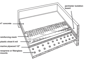
Figure 1:
Layered Floor
Diagram
(David Miles Huber
Robert, E. Runstein)
Figure 1 displays a diagram of a layered floor with labelled materials. A layered floor should be considered for a more budget friendly option when coming to flooring, as shown on figure 1 there are multiple layers with a concrete finish, on top of this concrete, thick carpet should be installed for absorption of more high frequency sound. (Absorption will be expanded upon in section 4). The layered floor will also prevent air and structure-borne noise.
2.2 Roofing
A layered roof should be considered to protect against the environment and to also yield some good airborne noise protection. An example would be “RBM” (BriggsAmasco 2018). If the room in question is in a building already, the common problem of foot traffic occurs, where low frequency, structure borne noise from above leaks down to the lower level through the ceiling, to reduce this, a “spring support system” could be utilised (David Miles Huber, Robert, E. Runstein., 2010).
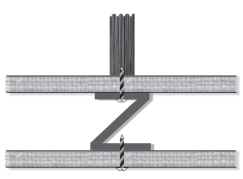
Figure 2:
Z Suspension
Diagram
(David Miles Huber
Robert, E. Runstein)
Figure 2 shows a Z suspension which hangs a fake ceiling, these are screwed to the ceiling joists which sound primarily travels through, the soundis then channelled into the fake ceiling and diffused.
2.3 Walling and Insulation
Brick is very durable and will provide acoustical benefit, preventing airborne noise. Brick has a much higher TL value than various building materials like wood.
For insulation, there is only one viable option which is spray foam, this fills all gaps and crevices that air may be able to travel further reducing airborne noise, spray foam is also very dense and therefore will have high absorption coefficient at higher frequencies, meaning more noise reduction and room isolation.
2.4 Doors
Doors are an obvious weak spot in studios as air can freely flow in and out through the gaps it provides, weather stripping counteracts this and seals the gaps around the door. However more professional and effective solution entails using multiple doors to create ‘sound lock’ spaces.

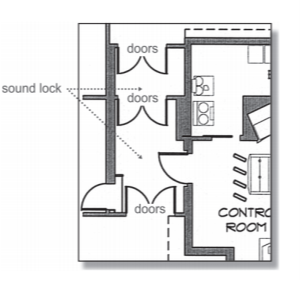
Figure 3:
Sound Lock Studio
Design Diagram
(David Miles Huber
Robert, E. Runstein)
Figure 3 shows a studio design diagram where the multiple doors are creating ‘sound locks’, this space acts as a barrier between the studio and the exterior room, isolating the interior room more. This sound lock usually has acoustic treatment in it to absorb and defuse any escaping sound from the studio space or live room space, adding an extra layer that sound needs to travel through, reducing noise further.
As for the door itself, solid wooden doors are more expensive, but have a much higher TL value than a hallow wooden door.
2.5 Other Techniques for Room Isolation and Noise Reduction
Risers elevate the drum kit off of the floor and defuse the energy from it before it can get to the floor, therefore reducing the structure-borne noise, this is a very similar concept to the suspended room.
3. Room Modes and Room Shape
3.1 Room Modes
Room modes are most commonly defined as resonances which occur in a room. These resonances cause sound to attenuate and amplify in different positions inside the room due to “phase cancellation and reinforcement” (David Miles Huber, Robert, E. Runstein., 2010). Room modes are created when sound waves travel and reflect between two or more objects and create standing waves, these standing waves have fundamental frequencies and are also directly proportional to the room dimensions.
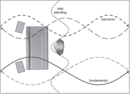
Figure 4:
Room Mode
Node
 /Standing Wave
Diagram
(David Miles Huber
Robert, E. Runstein)
Anti-Node

Figure 4 shows a visualisation of standing waves in a room and how room modes work, with the anti-nodes amplifying sound and nodes creating attenuations in the room. This also shows how negatively it can affect the listener creating a completely false image of the sound if in one of these modal positions. Harmonic frequencies are always multiples of the fundamental frequencies.
The fundamental resonant frequency occurs at the frequency where the distance between two parallel walls is equal to half a wavelength of a specific frequency. The equation to calculate this is expressed:
f = c / 2L
Where f = frequency (Hz)
And c = Speed of sound (m/s)
And L = Length of the room
This equation is used to calculate axial room modes in particular. There are different types of room modes which are all created slightly differently.
3.2 Types of Room mode
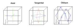 There are three main types of room mode; axial, tangential and oblique.
Figure 5:
Room Mode Types
(Bluefrogaudio
2015)
Figure 4 shows all three types of room modes and potential pathing options for each.
Axial Room modes use parallel surfaces to occur over one dimension, these are the strongest modes in intensity out of the three.
Tangential use four surfaces, reflecting from 2 corners is also possible. Tangential modes are around half the intensity of axial modes.
Finally, Oblique modes are formed using 6 surfaces, and these are around a quarter the intensity of Axial.
All room modes in a 3 dimensional space with parallel surfaces can be calculated with the equation:
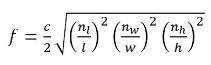
Figure 6:
Room Mode
Equation
(Pro Audio
Encyclopaedia
Foreman, C.)
where f = frequency (Hz)
and c = speed of sound (m/s)
and nl = mode of the room length (Integer)
and nw = mode of the room width (Integer)
and nh = mode of the room height (Innteger)
and L, B, H = Length, Width, Height (Meters)
3.3 Room Shape
As seen from the discussion above and figure 5, room shape can impact the regularity of room modes, therefore a conclusion can be made that angled walls would be the better option as it would eliminate most axial modes occurring from parallel surfaces, however this would require new calculations as room modes would still occur. A studio space is totally possible in a square or rectangular space, however extensive acoustic treatment will be needed.
4. Acoustic Room Treatment
Acoustic treatment is a necessity for any studio, and understanding its effects, drawbacks and benefits is crucial.
There are two main acoustical characteristics of sound which relate heavily to treatment. Reflection and absorption.
4.1 Reflections and Reverberation Time
One of the most important characteristics of sound is its ability to reflect off of barriers that it encounters at angles equal to its angle of incidence. Using these reflections, sound can be manipulated to alter the frequency response of a room, specialising the room for certain tasks. In terms of a mixing room, the end goal would be to deaden the room as much as possible, which means the less reflections the better.
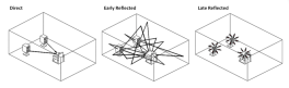 Figure 7:
Reflection Types
(Acoustic Frontier
2015)
Figure 7 displays a diagram showing the different types of reflections, firstly there is direct sound, which is the original, unaffected sound from the speaker, next there is early reflections which happen around “50 – 80 milliseconds” (Mcgill University 2004-2018) after direct sound and usually only reflects off one surface before reaching the listener, this sound is not perceived differently from the direct sound and therefore one cannot distinguish between the two ,however because the sounds characteristics have been altered from coming into contact with the room, the sound is no longer a true representation of the original. Any sounds that reach the listening position after the time boundaries for early reflections have been exceeded are known as late reflections, these reflections makeup the reverberant characteristic of sound. The reverberant sound level is reached once “the rate at which energy is supplied by the source is equal to the rate at which sound is absorbed by the room and its contents” (Mcgill University 2004-2018). Reverberation is a problem as the sound that it is made up of has been completely altered by the room and therefore is a false version of the original sound, making any professional mixing impossible.
Reverberation time or RT60 gives an overview of how long these late reflections are taking to decay and refers to how long a sound takes to decrease by 60dB (hence the ‘60’) from the original level it was at. For a mixing room, the goal is to get this RT60 down as low as possible and as reverberation is frequency dependant, to also make sure all frequencies reverberation time has a flat response, meaning if 70Hz had an RT60 of 0.2, all other frequencies should have a similar RT60, otherwise imbalances in the room occur and different frequencies are amplified and attenuated. Too much treatment can also be a bad thing, creating low end boosts with the high end being cut. The equation for calculation reverberation time is:
Figure 7.1 RT60 = V × 0 049 / Sa (in feet)
RT60 = V × 0 161/ Sa (in metres)
Where V = Volume of the room (m3)
And A = Average absorption coefficient of the room
And S = Total surface area (m2)
This is called the Sabine’s Equation. As sabines equation shows, everberation time is directly proportional to the room volume and also the absorption coefficients of the materials in it.
4.2 Absorption and absorption coefficients
Absorption is essentially the inverse of reflection, when sound waves hit a material some of the energy from that sound wave will be absorbed by it, reducing the sound level, before the wave reflects back off. A ratio called the absorption coefficient can be calculated to determine the amount absorbed energy relative to the amount reflected and can be expressed as:
Figure 7.2 A = Ia / Ir
Where A = Absorption coefficient
And Ia = Sound level absorbed (dB)
And Ir = Sound level reflected (dB)
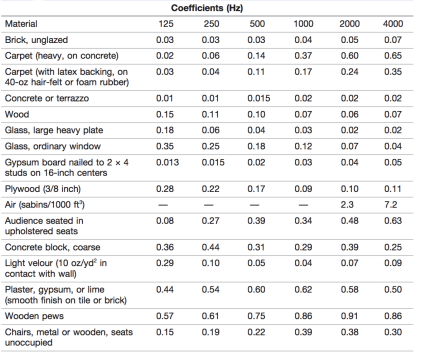
Figure 8:
Absorption Coefficient Table (David (Miles Huber
Robert, E. Runstein)
Figure 8 shows an absorption coefficient for a selected collection of materials and objects. Every material has an absorption coefficient, however for practical uses tables have to be condensed. Every value has been derived for the equation in figure 7.2, these values can be converted to percentages, for example 0.22, means that there will be a 22% reduction of energy from a sound hitting the material and a 78% reflection (1 being full 100% absorption of the sound, and 0 being 100% reflection). As shown in figure 8, these values are also frequency dependant, with octave bands showing at the top. This means materials absorb sound by varying amounts at different frequencies, which means an array of treatments have to be used for separate frequencies. The total amount of absorption inside a room can be calculated with the equation:
Figure 8.1 “Aave = (s1a1 + s2a2 +…+ snan)/S” (David Miles Huber, Robert, E. Runstein., 2010).
Where A = total room absorption
And s1, s2, sn = different surface areas inside the room
And a1, a2, an = different absorption coefficients inside the room
Varying treatment is needed for different frequencies, to determine what treatment type to use for these differing frequency, the Schroeder Frequency needs to be found.
4.3 Diffusion
Diffusion takes the sound and spreads its energy out evenly, decreasing focused energy. This keeps soundwaves from grouping up or overlapping (room modes) reducing the sounds potential to be troublesome.
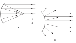
Figure 9:
Concave and
Convex
(F. Alton, Everest.
Ken C. Pohlmann)
Figure 9 displays a diagram of two types of surface shape; Concave (A) and Convex (B). Concave focuses sound energy as can be seen on figure 9, this is bad for studio spaces as this can cause amplification spots in the room where intensity is increased, while Convex (B) is perfect for getting rid of these amplified spots. By spreading out the sound in random directions there is less chance for sound to overlap and reinforce, this is known as diffusion. Quadratic diffusion is effective from 200Hz and upwards.
4.4 Schroeder Frequency
The Schroeder frequency is the frequency at which the divide between two sections of the room occur. Schroeder said there were two parts to a room, the Resonator, and the Reflector, these two parts require different acoustic treatment methods in order to be effectively controlled. The resonator, refers to unwanted pressure due to the energy not being able to fit inside the room (lower frequencies with longer wavelengths) which are classed as Waves and need either Diaphragmatic, Membrane, or Helmholtz to be properly controlled, while the Reflector refers to mid-high frequencies reflecting off the walls of the space, known as Rays, which require absorption methods like Acoustic Foam to be controlled. The Schroeder Frequency can be calculated with the equation:
Figure 9.1 “RT60sec / Volc.um Quotient *2000 (Constant)” (Acoustic Fields, 2016)
Where RT60 = Reverberation Time of the room (Seconds)
And Vol = Volume of the room (m3)
The Schroeder frequency again feeds into the balancing act which is room acoustics. Not enough reduction on pressure creates a low-end boom effect and too little will leave the studio space without any low frequencies at all.
5. Speaker Placement
5.1 Placement Angle and Height
Speakers should be on stands at least one meter away from each wall, the stands reduce resonances between the floor and speaker, which cause speakers to sound muddy, while spacing the speakers from the wall will eliminate any possibilities of early reflection interference. As sound increases in frequency, it becomes more directional, therefore the tweeters need to be at ear height slightly angled toward the listener, therefore the sound is traveling directly into the listeners ears, which creates a clearer sound and ensures balance between low and high end.
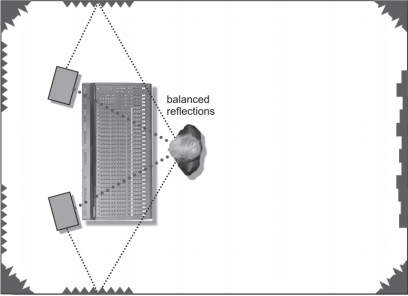
Figure 10:
Balanced
Reflections
(David Miles
Huber. Robert, E.
Runstein)
Figure 10 displays a diagram of how balanced reflections can be achieved, symmetry is very important in regard to speaker placement and on figure 10 it can be seen that the acoustic treatment is the same on both walls, creating the same environment for both speakers allowing reflections to act the same on both sides. If balanced reflections are not achieved, a bad stereo image can be the result.
5.2 Critical Distance
For an effective stereo image and sound, speakers need to be the same distance from each other as they are from the listening position, creating an equilateral triangle as shown on figure 10. The optimal parting distance between the speakers and distance from the speakers is determined by critical distance.
Critical distance refers to the position in the room at which reverberant sound and direct sound are equal.
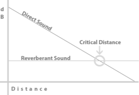
Figure 11:
Critical
Distance
(TeachMeAudio
2018)
Figure 11 displays a graph showing how critical distance works. The reverberant sound can be seen which is a constant throughout the room, and it can be seen that as direct sound travels over a distance it slowly decreases, the rate of this is 6dB per doubling of distance from the speaker (According to inverse square law). The point at which these two intersect is then known as the critical distance.
Critical Distance can be calculated with the equation:
Dc = 0.141 RQ
Where R = Room Constant
And Q = Directivity factor of speaker
The room constant can be calculated with the equation:
“R = A / (1 – am)
= Σ Si αi / (1- αm)” (Engineering Toolbox, 2003)
Where A = Total room absorption
And am = Mean absorption coefficient
And Si = different surface areas of the room
And ai = different absorption coefficients in the room
And finally, the Directivity Factor of the speaker can be calculated with the equation:
“R = SA / 1 – A” (Winer, E., 2013, pp. 304-306)
Where S = total surface area
And A = mean absorption coefficient
6. Conclusion
This report has discussed key acoustic principles associated with studio design including; Architectural properties, sound isolation, room modes, reflection, absorption and diffusion, Schroder frequency and speaker placement in regard to height, angle, spacing and critical distance.
Reference List
- Winer, E. (2018). The Audio Expert, Everything You Need to Know About Audio. (2nd ed.). Abingdon: Focal Press. pp. 304-306.
- Engineering ToolBox, (2003). Propagation of Sound Indoors – Room Constant. [Online]. [26 December 2018]. Available from: https://www.engineeringtoolbox.com/sound-propagation-indoor-d_72.html
- Foley D., (2003), Schroeder Frequency. [Online]. [26 December 2018]. Available from:
- Gary, P. Scavone Mcgillca. 2019. Room Acoustics [Online]. [27 December 2018]. Available from: https://www.music.mcgill.ca/~gary/618/week3/room_acoustics.html
- Huber, D.M. & Runstein, R.E., (2010). Modern Recording Techniques. (7th ed.). Burlington: Focal Press. Chapter 3, pp. 81 – 109.
- Briggsamascocouk. 2019. RBM. [Online]. [23 December 2018]. Available from: https://briggsamasco.co.uk/what-we-do/rbm/
List of Figures
- Huber, D.M. & Runstein, R.E., (2010). Modern Recording Techniques. (7th ed.). Burlington: Focal Press. Chapter 3, pp. 85.
- Huber, D.M. & Runstein, R.E., (2010). Modern Recording Techniques. (7th ed.). Burlington: Focal Press. Chapter 3, pp. 87.
- Huber, D.M. & Runstein, R.E., (2010). Modern Recording Techniques. (7th ed.). Burlington: Focal Press. Chapter 3, pp. 89
- Huber, D.M. & Runstein, R.E., (2010). Modern Recording Techniques. (7th ed.). Burlington: Focal Press. Chapter 3, pp. 98
- Bluefrogaudiocouk. 2019. Room Modes. [Online]. [25th December 2018]. Available from: http://www.bluefrogaudio.co.uk/room modes.html
- Foreman, C. 2015. Acoustic Fundamentals [Online]. [24th December 2018]. Available from: http://proaudioencyclopedia.com/acoustical-fundamentals/
- Acousticfrontierscom. 2015. Early Reflections 101. [Online]. [25th December 2018]. Available from: http://www.acousticfrontiers.com/early-reflections-101/
- Huber, D.M. & Runstein, R.E., (2010). Modern Recording Techniques. (7th ed.). Burlington: Focal Press. Chapter 3, pp. 103
- Huber, D.M. & Runstein, R.E., (2010). Modern Recording Techniques. (7th ed.). Burlington: Focal Press. Chapter 3, pp. 95
- Everest, F.A & Pohlmann , K.C (2009). Master Handbook of Acoustics. (5th ed.). New York: McGraw-Hill. Chapter 9, pp. 132.
- Teachmeaudiocom. 2019. Recording Considerations. [Online]. [25th December 2018]. Available from: https://www.teachmeaudio.com/recording/sound-reproduction/recording-considerations/
Bibliography
- Winer, E. (2018). The Audio Expert, Everything You Need to Know About Audio. (2nd ed.). Abingdon: Focal Press. pp. 304-306.
- Engineering ToolBox, (2003). Propagation of Sound Indoors – Room Constant. [Online]. [26 December 2018]. Available from: https://www.engineeringtoolbox.com/sound-propagation-indoor-d_72.html
- Bluefrogaudiocouk. 2019. Room Modes. [Online]. [25th December 2018]. Available from: http://www.bluefrogaudio.co.uk/room modes.html
- Acousticfrontierscom. 2015. Early Reflections 101. [Online]. [25th December 2018]. Available from: http://www.acousticfrontiers.com/early-reflections-101/
- Newell, P (2013). Recording Studio Design. (3rd ed.). Burlington: Focal Press. Chapter 11, pp. 339-341.
- Foley D., (2003), Schroeder Frequency. [Online]. [26 December 2018]. Available from: https://www.youtube.com/watch?v=-YtiT3U1FSM
- Gary, P. Scavone, Mcgill University,(2004), Room Acoustics. [Online] Available at: https://www.music.mcgill.ca/~gary/618/week3/room_acoustics.html [Accessed 24th December]
- Huber, D.M. & Runstein, R.E., (2010). Modern Recording Techniques. (7th ed.). Burlington: Focal Press. Chapter 3, pp. 81 – 109.
- Briggsamascocouk. 2019. RBM. [Online]. [23 December 2018]. Available from: https://briggsamasco.co.uk/what-we-do/rbm/
- Teachmeaudiocom. 2019. Recording Considerations. [Online]. [25th December 2018]. Available from: https://www.teachmeaudio.com/recording/sound-reproduction/recording-considerations/
- Ballou, G.M., (2008). Handbook for Sound Engineers. (4th ed.). Burlington: Focal Press. Chapter 2, pp. 30 – 31.
- Everest, F.A & Pohlmann , K.C (2009). Master Handbook of Acoustics. (5th ed.). New York: McGraw-Hill. Chapter 9, pp. 132.
Cite This Work
To export a reference to this article please select a referencing stye below:
Related Services
View all


DMCA / Removal Request
If you are the original writer of this essay and no longer wish to have your work published on UKEssays.com then please click the following link to email our support team:
Request essay removal